The GD32VF103 is an inexpensive 32 bit RISC-V CPU that integrates a bunch of peripherals. In other words, it's a cheap RISC-V microcontroller (MCU). This article describes how to hook it up, to set up an development environment and do some first steps with its peripherals.
Characteristics
The GD32VF103 exists in several variants, e.g. the Seeed development boards are built around the GD32VF103CBT6. Some of its characteristics:
- RISC-V 32 bit instruction set: RV32IMAC (i.e. no floating point extension)
- 108 MHz CPU frequency (can be clocked lower)
- 32 KiB RAM
- 128 KiB flash
- 3.3 V supply voltage
- 2 stage instruction pipeline
- Realtime clock (with periodic and alarm interrupt, can be calibrated)
- 6 16-bit timers
- 2 watchdogs
- many external interrupts
- several GPIO and ADC pins
- a bunch of UART/USART/SPI units (e.g. 5 U(S)ART and 3 SPI)
Looking at the peripherals, i.e. their registers, GigaDevice's GD32VF103 RISC-V MCU arguably is quite similar to GigaDevice's GD32F103 Arm MCU which in turn is similar to the ST STM32F103 Arm MCU (i.e. an Arm Cortex-M3 MCU, commonly used on the compact 'Blue Pill' development boards).
Despite being 32 bit CPUs all these MCUs have one curious property in common: almost all of their memory-mapped (special purpose) registers are only 16 bit wide. That means they are 32 bit registers, but only the least significant 16 bits are used. Thus, many registers used to configure and interface with peripherals that require more than 16 bits are split over two concrete ones (i.e. a high and low part), such as the RTC counter value (32 bits mapped via 2 times 16 bit) or the RTC alarm register (20 bits mapped via 16 bit and 4 bit halves).
Of course, such splitting is tedious and error-prone. Especially when reading such registers, one has to think about atomic access, since there might be a race where the low part wraps around just after you have read it and thus the high part might get incremented just before you are reading it. (analogous issue when you start with the high part)
Development Boards
Seeed Studio sells several development boards built around the GD32VF103. The most compact one is the Sipeed Longan Nano v1.1 which is available for 10 dollars or euros or so. The rest of this article concentrates on this board.
The Longan Nano has similar dimensions like an Arm Blue Pill board or some of the compact Arduino ones, such as the Arduino Micro or Mini Pro.
Some notable features of the Longan Nano v1.1 board:
- it comes with a small 160x80 pixel TFT display attached to an SPI port (detachable)
- low-speed external 32.768 kHz quartz oscillator for use with the RTC on GPIO pins C14 and C15 (LXTAL)
- high-speed external 8 MHz quartz oscillator (HXTAL) from which the 108 CPU clock is synthesized
- RGB LED on GPIO pins C13, A1 and A2
- on-board push-button on GPIO pin A8 (boot0 button with external pull-down)
- micro-SD card slot
- 3.3 V voltage regulator (max: 6 V) at 5V pin, non-regulated supply pin available (pin 3V3)
- JTAG header
- power LED
- USB interface
Assembling
As it's common with these boards, it comes with the side-headers not soldered yet.
When the pins C14 and C15 aren't needed for IO and instead the RTC should be driven by the external quartz connected to these pins it's recommended to not solder any header to those pins. That means simply break the supplied header two times to connect just the VBAT pin and the pins RESET until C13. This should improve the performance of the external quartz somewhat.
However, even if C14/C15 are soldered and connected to a bread-board it isn't really a catastrophe for RTC usage, since the RTC should be calibrated anyways and such calibration should compensate some of the issues with that. Besides slight RF issues perhaps. Purists might even want to cut the traces to the C14/C15 pins as early as possible.

Connecting
In theory, the Nano supports programming it over the onboard USB interface via the DFU mode. However, there are 2 issue with that:
- It doesn't support auto-reset and thus requires a very tedious and error-prone manual procedure, i.e. pressing the boot0 booting before pushing briefly reset and then releasing again boot0 sequence before the actual flashing
- It's only supported by the legacy gd32vf103-sdk framework which is incomplete, buggy and unmaintained.
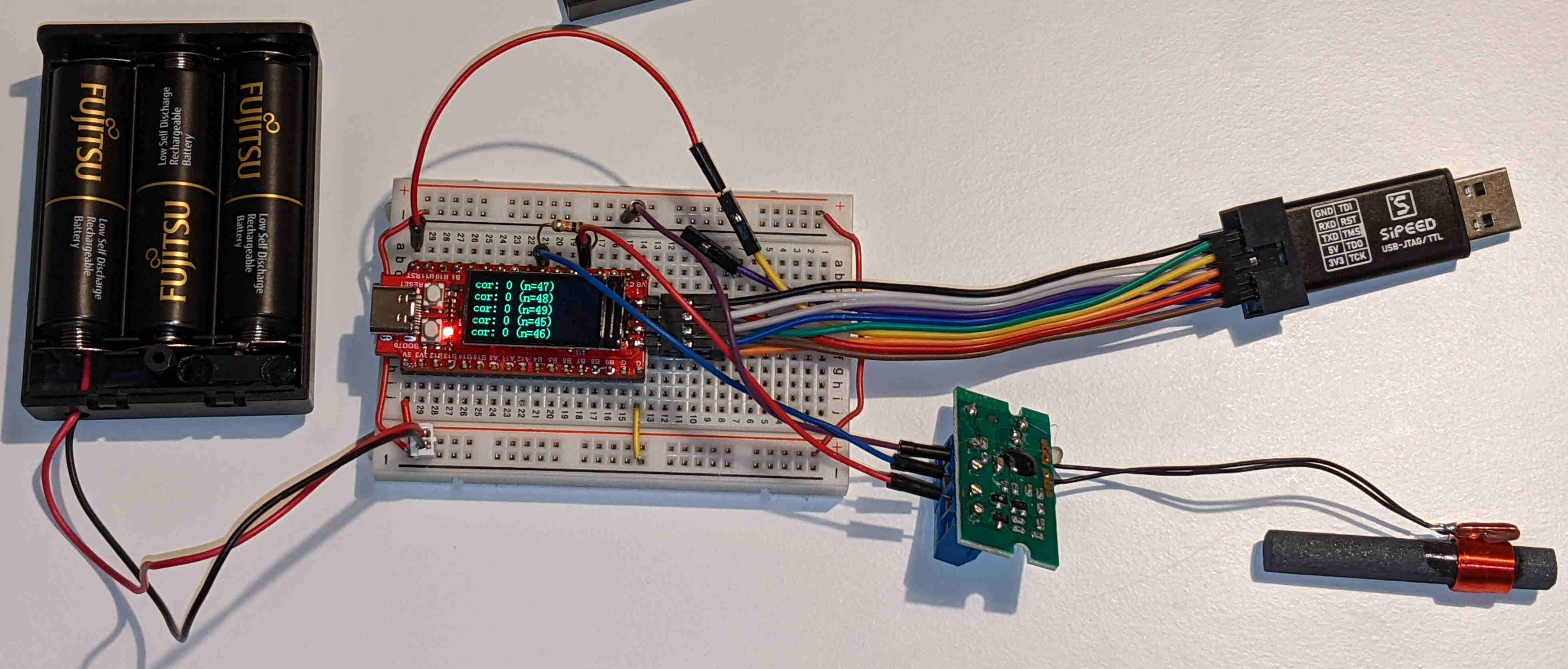
Thus, one really needs a JTAG adapter for programming the Longan Nano, such as the Sipeed USB-JTAG/TTL RISC-V Debugger which also costs around 10 Dollars/Euros.
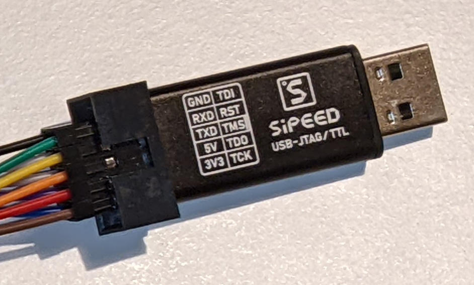
NB: The Vendor Seeed Studio apparently sells (or had sold) different variants of that JTAG adapter under the same SKU. The item I ordered at the end of 2021 through Antratek (who sourced it from Seeed Studio through eVatmaster Consulting GmbH, production date 2021/05/15) comes with 3.3 V and 5 V supply pins (which is quite convenient) whereas the Seeed Studio stock photo has that pin marked as NC (not connected) and GND (as of May 2022). Perhaps that's just an outdated photo and all currently sold devices have the supply pins. But one can't be sure. I've notified the vendor via a Disqus comment, but the moderators didn't approve it.
Note that both the Nano and the Sipeed JTAG device have a double row header, however, the pins don't match 1:1, back to back. Especially the reset pin isn't part of the Nano JTAG header.
When orienting the Nano with USB-C port to the left and the Sipeed JTAG device to the right (USB-connector to the right), markings on top, the pins read top-down:
| Location | Pins |
|---|---|
| JTAG back-row | GND, RXD, TXD, 5V, 3V3 |
| JTAG front-row | TDI, RST, TMS, TDO, TCK |
| Nano back-row | JTDO, JTDI, JTCK, JTMS |
| Nano front-row | GND, TX0, RX0, 3.3V |
| Nano top header | RESET |
Thus, the Nano/JTAG should be connected like this:
| Nano | JTAG/TTL device |
|---|---|
| JTDO | TDO |
| JTDI | TDI |
| JTCK | TCK |
| JTMS | TMS |
| RESET | RST |
| GND | GND |
| TX0 | RXD |
| RX0 | TXD |
| 3.3V | 3V3 |
| nothing | 5V |
Powering
When not powering the Nano from a JTAG adapter, it can be powered in several alternative ways:
- connecting a USB power-bank to the USB-C port
- connecting a battery (pack) with voltage between 3.3 V and 6 V to the voltage regulator (i.e. the 5V pin) and ground (GND pin).
- connecting a 3.3 V power source directly to the 3.3V pin (i.e. left of the 5V pin), i.e. without using the onboard voltage regulator
The VBAT pin is for connecting a 2.6 to 3.6 V battery to power the RTC (in the battery backup domain) when the main voltage supply is turned off. When no extra RTC battery is required, the manual recommends to connect VBAT to VDD (i.e. to the 3.3V pin) and place a 0.1 µF decoupling capacitor between VBAT and ground. According to the schematics, there should be an unpopulated R8 somewhere on the PCB which could be closed in order to follow the recommendation.
Similarly to the Arduino Mini Pro, the Nano board isn't really optimized for low-power. First of all, it has a power-indicator LED. Also, the onboard voltage regulator (MicrOne ME6211C33) isn't the most efficient one (I_q=60 µA or so, whereas - say - the MCP1700 has I_q=1.6 µA and a lower voltage drop).
One could try the following modifications in order to decrease the power usage:
- Desolder the power-on LED (DS1) or its series resistor (R6=2kOhm).
- Desolder/remove the voltage regulator and use an more efficient one, externally, if required.
Especially the first modification looks more complicated with the Nano than with the Arduino Mini Pro, because the SMD parts are grouped together more tightly. Unfortunately, unlike with the original Sparkfun Arduino Mini Pro there is no Jumper that could simply be disconnected (desoldered) to disconnect the onboard voltage regulator and power-on LED.
Development Environment
First of all, the JTAG device likely needs some additional udev
rule such that its device files can be accessed by a normal user. For
example, for the Sipeed device one could drop a config snippet
like the following into /etc/udev/rules.d, e.g. in a file named
99-platformio-udev.rule:
ATTRS{idVendor}=="0403", ATTRS{idProduct}=="6010", MODE="0660", GROUP="dialout", ENV{ID_MM_DEVICE_IGNORE}="1", ENV{ID_MM_PORT_IGNORE}="1"
Make then sure that your user is part of the dialout group.
The simplest way to start development is to use PlatformIO which supports the GD32VF103/Longan Nano. PlatformIO can be used exclusively from the command line, but there is also a PlatformIO VSCode plugin, which VSCode fans might prefer.
In case PlatformIO isn't packaged yet for your favourite Linux distribution you can install it like this:
python3 -m venv ~/local/platformio
source ~/local/platformio/bin/activate
pip install platformio
cd ~/local/bin
ln -s ../platformio/bin/pio
First test is to query the Longan Nano support:
$ pio boards longan

Platform: gd32v
============================================================================================
ID                       MCU            Frequency    Flash    RAM    Name
-----------------------  -------------  -----------  -------  -----  -----------------------
sipeed-longan-nano       GD32VF103CBT6  108MHz       128KB    32KB   Sipeed Longan Nano
sipeed-longan-nano-lite  GD32VF103C8T6  108MHz       64KB     20KB   Sipeed Longan Nano Lite

Platform: nuclei
======================================================================================
ID                      MCU            Frequency    Flash    RAM    Name
----------------------  -------------  -----------  -------  -----  ------------------
gd32vf103c_longan_nano  GD32VF103CBT6  108MHz       128KB    32KB   Sipeed Longan Nano
There is a pitfall right there! The first platform gd32v uses the outdated and unmaintained legacy gd32vf103-sdk framework (cf. https://github.com/riscv-mcu/GD32VF103_Firmware_Library). Unfortunately, many Longan Nano examples found online are a few years old and thus do use this framework. Hence, one might be tempted to start with that. However, it's incomplete and buggy. Those examples that are using the gd32v platform are still instructive, though, because much of the API is also present in the Nuclei SDK. But some APIs changed so be prepared to adjust old examples when looking at them.
So the Nuclei platform it is. To create a new project:
mkdir first-longan-test
cd first-longan-test
pio project init --board gd32vf103c_longan_nano --ide vim
This creates a platform.ini file that reads like this:
[env:gd32vf103c_longan_nano]
platform = nuclei
board = gd32vf103c_longan_nano
framework = nuclei-sdk
NB: With the nuclei platform the default upload_protocol is rv-link which works fine with the Sipeed JTAG device.
For integration with Vim quickfix mode you can create a simple makefile like the following:
.PHONY: all
all: build


.PHONY: build
build:
        pio run

.PHONY: upload
upload:
        pio run --target upload
For a first test run, to check whether the edit/compile/flash cycle works, you can blink the on-board LED:
#include <gd32vf103.h>
#include <gd32vf103_gpio.h>
#include <gd32vf103_rcu.h> // reset and clock unit

#include <stdbool.h>


static void switch_led(bool b)
{
    // inverse logic with the onboard red LED
    if (b)
        GPIO_BC(GPIOC)  = GPIO_PIN_13; // bit-clear
    else
        GPIO_BOP(GPIOC) = GPIO_PIN_13; // bit-operate

    // alternatively:
    // gpio_bit_write(GPIOC, GPIO_PIN_13, !b);
}

static void blink3(unsigned x)
{
    for (unsigned i = 0; i < 2; ++i) {
        switch_led(true);
        delay_1ms(x);
        switch_led(false);
        delay_1ms(223);
    }
    switch_led(true);
    delay_1ms(x);
    switch_led(false);
}

int main()
{
    rcu_periph_clock_enable(RCU_GPIOC);
    gpio_init(GPIOC, GPIO_MODE_OUT_PP, GPIO_OSPEED_50MHZ, GPIO_PIN_13);
    switch_led(false);

    for (;;) {
        blink3(223);
        delay_1ms(3 * 223);

        blink3(3 * 223);
        delay_1ms(3 * 223);

        blink3(223);
        delay_1ms(5 * 223);
    }

    return 0;
}
Just drop this example into the src directory as - say - main.c and call make.
C++
One can also use C++ (or a subset of C++) with this MCU. However, not all of the SDK headers are C++ friendly, i.e. not all of them wrap themselves with:
#ifdef  __cplusplus
extern "C" {
#endif

// [all the declarations ...]

#ifdef  __cplusplus
}
#endif
Thus, from C++ one has to include the SDK headers like so:
extern "C" {
#include <gd32vf103_rcu.h>
#include <gd32vf103_gpio.h>
}
NB: The next Nuclei SDK release will have all such headers in a C++ friendly state (cf. my merged pull-request).
Also, interrupt handlers must be wrapped in a similar way.
NB: Although the Nuclei SDK doesn't compile with
-fno-exceptions (unlike e.g. the GCC/AVR SDK that targets 8 bit
MCUs), C++ exceptions simply don't work, out of the box.
Code that throws and catches exceptions compiles, but the linker
then warns about _getpid and _kill always failing (due to not
being implemented). Also, even a small example with a single
throw/catch increases precious flash space usage by 40 KiB.
FWIW, when actually disabling exceptions (by setting
build_flags = -fno-exceptions in platformio.ini) compiling a
a small C++ example leads to 192 bytes of flash space being saved.
Interrupts
Only letting LEDs blinks in a busy-loop gets boring, fast.
Configuring interrupts on the GD32VF103 is a bit more involved than with a - say - ATmega328p, because the interrupt system is more advanced.
For example, to configure an external interrupt for pin A0:
rcu_periph_clock_enable(RCU_AF);
rcu_periph_clock_enable(RCU_GPIOA);

// configure internal pull-up
gpio_init(GPIOB, GPIO_MODE_IPU, GPIO_OSPEED_50MHZ, GPIO_PIN_0);

// alternatively, with external pull-up/pull-down
// gpio_init(GPIOA, GPIO_MODE_IN_FLOATING, GPIO_OSPEED_50MHZ, GPIO_PIN_0);

gpio_exti_source_select(GPIO_PORT_SOURCE_GPIOA, GPIO_PIN_SOURCE_0);
exti_init(EXTI_0, EXTI_INTERRUPT, EXTI_TRIG_BOTH);

exti_interrupt_flag_clear(EXTI_0);
exti_interrupt_enable(EXTI_0);

// higher preempts lower, IRQ levels start at 1
ECLIC_SetLevelIRQ(EXTI0_IRQn, 1);
// doesn't preempt, but is a tie breaker for multiple pending ones
ECLIC_SetPriorityIRQ(EXTI0_IRQn, 1);
ECLIC_EnableIRQ(EXTI0_IRQn);

// interrupts aren't enabled, by default
__enable_irq();
There are several external interrupts and each can wake-up the CPU from sleep.
Sidenote: The CPU can be also be woken by configured events which should be faster.
The available interrupts can be looked up via:
grep IRQn ~/.platformio/packages/framework-nuclei-sdk/SoC/gd32vf103/Common/Include/gd32vf103.h
NB: Not every GPIO pin configured as input can have its own interrupt. For example, EXTI0_IRQn would be shared between pin 0 of each port group (e.g. B0 and C0). In addition, some pins are grouped into one interrupt such as EXTI10_15_IRQn for pins 10 to 15.
With the above setup handling an interrupt is as simple as overwriting a weak symbol, e.g.:
volatile bool some_value;

#ifdef  __cplusplus
extern "C"
#endif
void EXTI0_IRQHandler()
{
    if (exti_interrupt_flag_get(EXTI_0) != RESET) {
        // if it's an edge-triggered vectored interrupt then
        // the flag should be auto-cleared
        exti_interrupt_flag_clear(EXTI_0);

        // do as little work as necessary in the handler, e.g.
        some_value = gpio_input_bit_get(GPIOA, GPIO_PIN_0);
    }
}
To get a list of available interrupt handler symbol names:
grep 'weak.*Handler' ~/.platformio/packages/framework-nuclei-sdk/SoC/gd32vf103/Common/Source/GCC/startup_gd32vf103.S
Enabling an interrupt thus basically consists of the following steps:
- Enable the corresponding interface
- Configure the device
- Enable an interrupt at the device level
- Configure the interrupt controller (ECLIC)
- Enable interrupts globally
- Add an interrupt handler
For comparison, to configure the RTC period 'second' interrupt (not to be confused with the RTC alarm interrupt):
// [.. enable/configure RTC ..]
// prescale to 1 second (-1 because divider starts at 0 ...)
rtc_prescaler_set(32768 - 1);
rtc_lwoff_wait();
rtc_interrupt_enable(RTC_INT_SECOND);
rtc_lwoff_wait();

ECLIC_SetLevelIRQ(RTC_IRQn, 1);
ECLIC_SetPriorityIRQ(RTC_IRQn, 1);
ECLIC_EnableIRQ(RTC_IRQn);
The corresponding interrupt handler:
volatile static uint32_t rtc_ticks;

#ifdef  __cplusplus
extern "C"
#endif
void RTC_IRQHandler()
{
    if (rtc_interrupt_flag_get(RTC_INT_FLAG_SECOND) != RESET) {
        rtc_flag_clear(RTC_INT_FLAG_SECOND);
        ++rtc_ticks;
    }
}
A common use-case for an MCU is to let it sleep/idle most of the time (to conserve energy) and wait on an interrupt. With the GD32VF103 (and the Nuclei SDK) this can be achieved like this:
#include <gd32vf103_pmu.h>


    for (;;) {
        pmu_to_sleepmode(WFI_CMD); // wait for interrupt

        // go to work!

        // [..]
    }
Realtime Clock (RTC)
Like the STM32F103 and unlike the - say - ATmega328p, the GD32VF103 integrates a realtime clock (RTC) unit. The purpose of the RTC to keep track of time even when the MCU is in deep sleep, possibly wake it up via an alarm at some point in time and optionally generate a timer interrupt. When the MCU doesn't provide an RTC an alternative is to use an external one such as a PCF8523 or DS3231.
A common RTC design is that an additional external low-speed 32.768 kHz oscillator is used. This is also possible with the GD32VF103 and the Longan Nano board even connects the dedicated pins to such an external quartz, like Blue Pill boards do. See also the Assembling Section for how these pins can be used otherwise.
Configuring the RTC is a little bit involved since it is located in the 'battery backup domain' (such that the rest of the MCU can be powered down), it has several options for a clock source and many other aspects can be customized. Being in the backup domain leads to shadow registers that have to synced over an Advanced Peripheral Bus (APB).
For example, to set up the RTC for a periodic interrupt that triggers each second:
// enable power managemenet unit - perhaps enabled by default
rcu_periph_clock_enable(RCU_PMU);
// enable write access to the registers in the backup domain
pmu_backup_write_enable();
// enable backup domain
rcu_periph_clock_enable(RCU_BKPI);
// reset backup domain registers
bkp_deinit();
// set the results of a previous calibration procedure
// bkp_rtc_calibration_value_set(x);

// setup RTC
// enable external low speed XO
rcu_osci_on(RCU_LXTAL);
if (rcu_osci_stab_wait(RCU_LXTAL)) {
    // use external low speed oscillaotr, i.e. 32.768 kHz
    rcu_rtc_clock_config(RCU_RTCSRC_LXTAL);
    rcu_periph_clock_enable(RCU_RTC);
    // wait until shadow registers are synced from the backup domain
    // over the APB bus
    rtc_register_sync_wait();
    // wait until shadow register changes are synced over APB
    // to the backup doamin
    rtc_lwoff_wait();
    // prescale to 1 second
    rtc_prescaler_set(32768 - 1);
    rtc_lwoff_wait();
    rtc_interrupt_enable(RTC_INT_SECOND);
    rtc_lwoff_wait();
}

// enable interrupt for RTC
ECLIC_SetLevelIRQ(RTC_IRQn, 1);
// doesn't preempt, but is a tie breaker for multiple pending ones
ECLIC_SetPriorityIRQ(RTC_IRQn, 1);
ECLIC_EnableIRQ(RTC_IRQn);
Since the external low speed quartz has a frequency of 32.768 kHz, we have to let the RTC count exactly 32768 times in order to generate the second interrupt. As the counter starts at the prescaler value, wraps around at 0 and the interrupt is emitted at the top value we thus have to set the prescaler to the frequency minus one.
The different features of the RTC can be described in pseudocode like this:
RTC_unit:
    while unit_is_enabled:
        if second_irq_enabled:
            emit_second_interrupt()
        if alarm_irq_enabled && RTC_CNT == RTC_ALRM:
            emit_alarm_interrupt()
        if overflow_irq_enabled && RTC_CNT == 2**32 - 1:
            emit_overflow_interrupt()

        RTC_CNT = (RTC_CNT + 1) % 2**32 // observable after next tick!

        for RTC_DIV = RTC_PSC; RTC_DIV >= 0; --i:
            wait_for_next_tick()

            pulses = (pulses + 1) % 2**20
            if pulses == 0:
                for i = 0; i < RCCV; ++i:
                    wait_for_next_tick()
The upper-case variables are actual register (field) names that are also used in the GD32VF103 manual. They are:
| Field | Description |
|---|---|
RTC_CNT |
RTC counter (32 bits), incremented after RTC_PSC + 1 ticks |
RTC_PSC |
RTC prescaler (20 bits) |
RTC_DIV |
RTC divider (20 bits), current prescaler iteration, |
RTC_ALRM |
RTC alarm (32 bits), emit alarm after RTC_CNT equals RTC_ALRM + 1 |
RCCV |
Realtime clock calibration value (7 bits) |
More concretely, like almost all mapped peripheral
registers, in reality, those registers are split between a low a high part
(e.g. RTC_CNTL and RTC_CNTH), as
mentioned in the Characteristics Section.
Thus, reading the RTC_CNT counter accurately is tricky. See for example the utility function the Nuclei SDK contains (as of May 2022):
uint32_t rtc_counter_get(void)
{
    uint32_t temp = 0x0U;

    temp = RTC_CNTL;
    temp |= (RTC_CNTH << RTC_HIGH_BITS_OFFSET);
    return temp;
}
The order of the reads is guaranteed because RTC_CNTL and
RTC_CNTH are macros that expand to dereferenced pointers to
volatile declared memory locations. However, the issue here is that
RTC_CNTL might overflow and yield an increment of RTC_CNTH
after it's loaded into temp but before RTC_CNTH is loaded.
Thus, a more robust approach is to code it like this:
static uint32_t get_rtc_cnt()
{
    uint32_t old_h = RTC_CNTH;
    for (;;) {
        uint32_t l = RTC_CNTL;
        uint32_t h = RTC_CNTH;
        if (h == old_h) {
            uint32_t r = (h << 16) | l;
            return r;
        }
        old_h = h;
    }
}
This race condition isn't just a theoretical issue, one can easily verify that the probability of occurence is greater than zero by setting the prescaler to a low value (or zero), calling that function in a loop and adding some diagnostics code at the end of the loop (or setting a breakpoint there).
Since the prescaler register is 20 bit wide, the so called 'second' interrupt can be set up to trigger from every 1/32768 second up to half a minute, when using the 32.768 kHz oscillator.
The RCCV register field can be set in order to compensate for an
oscillator that runs too fast. Without any
compensation, the clock likely drifts by a few seconds per day
due to production variability, temperature variation and aging.
See also a follow-up article where I describe a concrete
calibration procedure.
NB: This is similar to the STM32F103 which also allows to set a 7 bit wide calibration value in the RTC clock calibration register BKP_RTCCR.
NB: The GD32F130's RTC also has a calibration register
(RTC_HRFC). In contrast to the other devices, its calibration
value is 9 bit wide and the register even contains a sign bit
(FREQI).
That means it's also possible to compensate for a clock that goes
too slow that way (i.e. by 'injecting' additional ticks after 2**20
real ticks happened).
Interestingly, the GD32VF103 manual explicitly states (Section 4.4.2 RTC signal output control register BKP_OCTL, page 59):
The value indicates how many clock pulses are ignored or added every 2^20 RTC clock pulses.
(emphasis mine)
But there isn't any sign bit documented. And the RCCV field isn't interpreted as two's complement value, either. Hence, it looks like this statement is wrong and that RTC ticks can only be skipped when setting a calibration value, as with the STM32F103.
Thus, to compensate a GD32VF103 (or STM32F103) RTC that goes too slow one has to decrement the prescaler, as well, and work from there.
LCD
The Longan Nano comes with a small 160x80 pixel color LCD display attached which is good for 20 column x 5 row text or even some graphics. It's connected to a ST7735S controller which in turn is attached to an SPI port. The controller implements the MIPI DCS standard which seems to be popular with such devices.
For quickly putting some text on the LCD, Müller's LCD and SPI classes are well suited and quick to start with.
For real graphics the gd32v-lcd library looks like a good starting point. (I haven't tested it, yet.)
To make some sense of the command byte sequences used in the libraries (and possibly modify/extend them) a look into the ST7735S datasheet is helpful.
It's even possible to directly printf() to the LCD by overwrite
the weakly defined write stub. See also
~/.platformio/packages/framework-nuclei-sdk/SoC/gd32vf103/Common/Source/Stubs/write.c
for the default implementation. That means if you define the
function yourself then it overwrites the weak default one.
Example:
extern "C"
ssize_t _write(int fd, const void* ptr, size_t len)
    {
        if (!isatty(fd))
            return -1;

        const char *p = (const char*) ptr;
        const char *end = p + len;
        for (; p != end; ++p)
            lcd.putChar(*p);

        return len;
    }
NB: The printf() implementation of the Nuclei SDK isn't
complete, e.g. some specifiers such as %f or %lu are simply
ineffective.
NB: The LCD and controller not just occupy the pins of the first SPI device, but also pins B0 (RS, i.e. command/data selection), B1 (reset), B2 (chip select, not connected to an external pin) which aren't included in kprasadvnsi's pinout diagram.
UART
The Nuclei SDK sets up the USART0 for 115200 baud UART during system start (cf. gd_com_init()), by default, and it
provides a stub such that printf() just works (cf. previous
section).
When using the Sipeed JTAG device one can connect to the UART like this:
picocom --baud 115200 --echo --imap lfcrlf /dev/ttyUSB1
NB: Since the Nano is flashed over JTAG the serial console can be kept open during flashing. This is convenient in comparison with the Arduino Mini Pro which are usually flashed also over the UART.
For details on how to use and configure the UART (or USART) see
also gd_com_init() in
~/.platformio/packages/framework-nuclei-sdk/SoC/gd32vf103/Board/gd32vf103c_longan_nano/Source/gd32vf103c_longan_nano.c
and the API in
~/.platformio/packages/framework-nuclei-sdk/SoC/gd32vf103/Common/Source/Drivers/gd32vf103_usart.c.
Müller's USART class is also instructive. If the default Nuclei's default serial parameters are sufficient you don't need to call its 'setup()` method.
Where to go from here
There is definitely less information available on the net about the GD32VF103 than about other microcontrollers. Also, the manual arguably is more minimal than - say - the ATmega328p one. Starting points:
- GD32VF103 Datasheet - i.e. for looking up electrical characteristics etc.
- GD32VF103 Manual - description of peripherals, register reference etc.
- Longan Nano Schematic
- Longan Nano pinout diagram
However, a good strategy is to look up peripherals and other
features in the manual, check out the register description there
and grep for the register names in the SDK. How the registers
are accessed there in the implementation of API functions often
paints a good picture how a feature is actually supposed to be
used. Example:
grep 'GPIO.*BOP' ~/.platformio/packages/framework-nuclei-sdk/ -r
As always, it doesn't hurt to search the web. There aren't many articles and examples available, but there are some. For example:
Andreas Müller's collection of Longan Nano C++ test programs - the test programs are well-structured and low-level access is often encapsulated in methods and classes in a meaningful way. The test projects cover a bunch of features such as SPI, LCD, GPIO, USART, I2C etc. The author has another repository that contains some more Longan Nano test programs and experiments. At least some of those seem to be based on examples distributed by GigaDevice.
As mentioned before, some examples use the legacy framework and need to adjusted, but often they are still quite helpful.
Another angle is to also search in the context of the STM32F103 (or just a keyword such as STM32 or STM32F1) since many features work in a similar way and there are even similarities in the API of the SDKs. For example, after reading a good tutorial on the STM32F103 one should be able to transfer much of the knowledge on how to access and configure GPIO pins to the GD32VF103.
Parts
As of May 2022, Seeed Studio has all RISC-V articles listed as out-of-stock (as well as all of their ARM and AVR boards). Also, shipping to Europe involves extra hassles due to import duties and taxes (either just extra charges or even dealings with customs).
Thus, it makes sense to look for these parts at a local distributor, such as Antratek (NB: as of May 2022, GD32VF103 devices are out of stock there, as well).
Another good alternative is to look at a global distributor such as Digi-Key. Using them from Europe is no problem as they take care of duty and customs. For convenience, direct links of the main parts referenced in this article:
- Sipeed USB-JTAG/TTL RISC-V Debugger (8.28 €)
- Longan Nano v1.1 (7.84 €)
And as of May 2022, they even have some of those still in stock.
Related MCUs
For a microcontroller, the GD32VF103 is relatively powerful. As mentioned before, it's similar to an Arm STM32F103. However, a typical STM32F103 Blue Pill board runs at 'just' 72 MHz, whereas the Longan Nano runs at 108 MHz.
For many tasks an 8 bit MCU such as the ATmega328p is sufficient, e.g. in the form of an Arduino Mini Pro which is clocked at 8 MHz (when using the 3.3V variant). Clocking an MCU lower saves some energy, but when running at a higher frequency the MCU might manage to finish a task faster such that it is able to go back to a low-energy sleep state earlier. FWIW, the GD32VF103 can be clocked at lower frequencies such as 8 MHz, as well.
Frequency and register size is one thing, but in terms of peripherals, in comparison with the ATmega328p, the GD32VF103 (and STM32F103) has more of everything. For example, more 16 bit timers, more fine grained timer dividers, a backup domain, an RTC, more external interrupts, etc.
The GD32VF103 isn't the only RISC-V microcontroller available. There is also the somewhat more powerful SiFive E310 (see also) which is a little bit more expensive, i.e. development boards are in the 30 € range. In contrast to the GD32VF103 it requires a 16 Mhz (and not 8 MHz) external oscillator.
Interestingly, the 32 bit RISC-V E310 does make use of the whole 32 bits in its memory-mapped peripheral registers, i.e. there is no splitting of fields at 16 bit boundaries as with the GD32VF103/GD32F103/STM32! The RTC counter is split, but only after 32 bits (i.e. the RTC counter is 48 bit wide). Speaking of the RTC, it's more limited than the previously mentioned ones. Most notably, it doesn't allow for any calibration!
Available (as of May 2022) are:
- LoFive R1 (Digi-Key) - created via a crowd-funding camgaign in 2019; the board isn't listed as supported in the PlatformIO sifive platform, i.e. its project wiki describes a custom makefile based SDK; it comes with 128 MBit flash and without an external low-frequency oscillator
- SparkFun RED-V Thing Plus (Digi-Key) - it's supported by PlatformIO; it comes with an additional low-frequency oscillator (32.768 kHz), on board LiPO charger, on-board USB JTAG device (which actually is an Arm Cortex-M4 MCU) and 32 MBit flash
Conclusion
The GD32VF103 in the form of the Longan Nano is great for quickly hooking up external peripherals for experiments. For example, printing some sensor data on the on-board LCD and/or collecting them over an UART/USB link to a host computer.
Per se, the GD32VF103 doesn't really have a unique selling point. Similar things can be archieved with other more popular microcontrollers. However, a big advantage over - say - Arm STM32F1 is that the GD32CVF103 has a RISC-V instruction set. Arguably, dealing with RISC-V assembly is a much more pleasant experience than working with - say - ARM assembly. Of course, good C/C++ compilers are available for many MCU architectures (including RISC-V, ARM, AVR), but a hand optimized function written in assembly may be required once in a while and verifying good code generation by the compiler in the hot path involves looking at an assembly dump.
It's perhaps not the best idea to start with the GD32VF103 if you are completely new to embedded programming and microcontrollers. An easier path probably is to start with a much more popular (and thus better documented) platform such as ATmega328p/Arduino or STM32. For example, the ATmega328p manual already is relatively accessible and literally for every feature there are at least 5 or so extensive and well-researched blog articles available. Also, with popular platforms there are likely multiple strong communities available that are approachable for discussion and help (such as dedidicated Stackexchange sites, Stackoverflow tags, dedicated forums, etc).